
Fuel pump lead is the distance travelled by the plunger from the point at which rise of the fuel cam starts (or the follower start lifting) till the piston of the unit in question reaches top dead centre or TDC (ignition DC). This article explains detailed procedure for measuring fuel pump lead with illustrations on an STX MAN B&W 6L23/30H marine auxiliary engine.
Procedure
Remove cam case inspection cover.
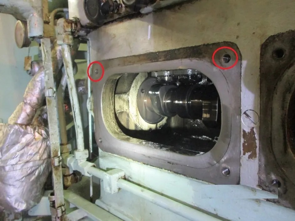
Camshaft inspection cover removed
Turn the engine flywheel and position the cylinder unit no.1 until fuel cam base circle is reached (approx. 40 degrees before TDC). Support measuring tool on the two bolts of the camshaft covering.
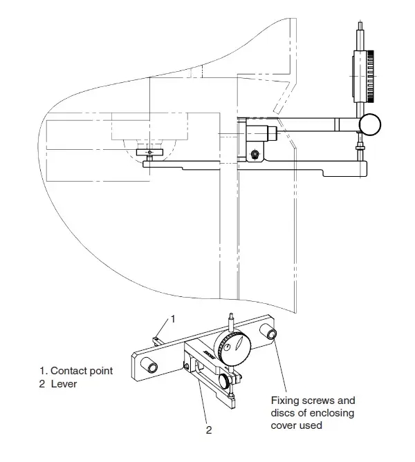
Fuel pump lead measuring tool
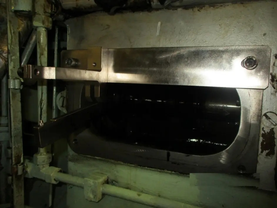
Measuring tool secured to camshaft door
While securing the tool, remember to align the ‘lever’ so that ‘contact point’ is fitted to the correct position.
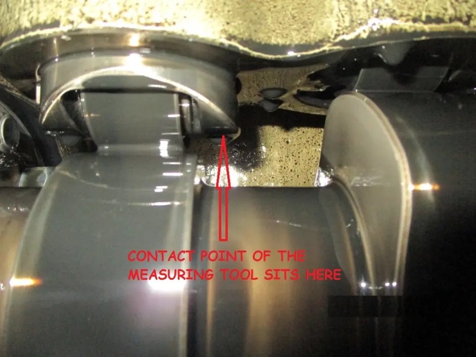
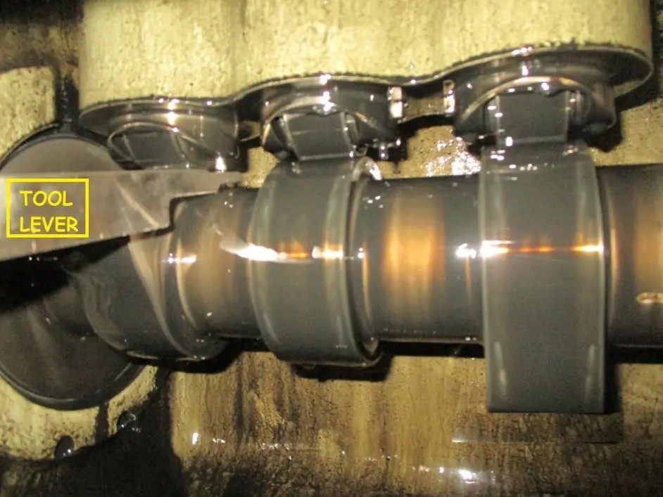
Measuring tool lever fitted in position
Insert dial gauge into the support and set it to zero.
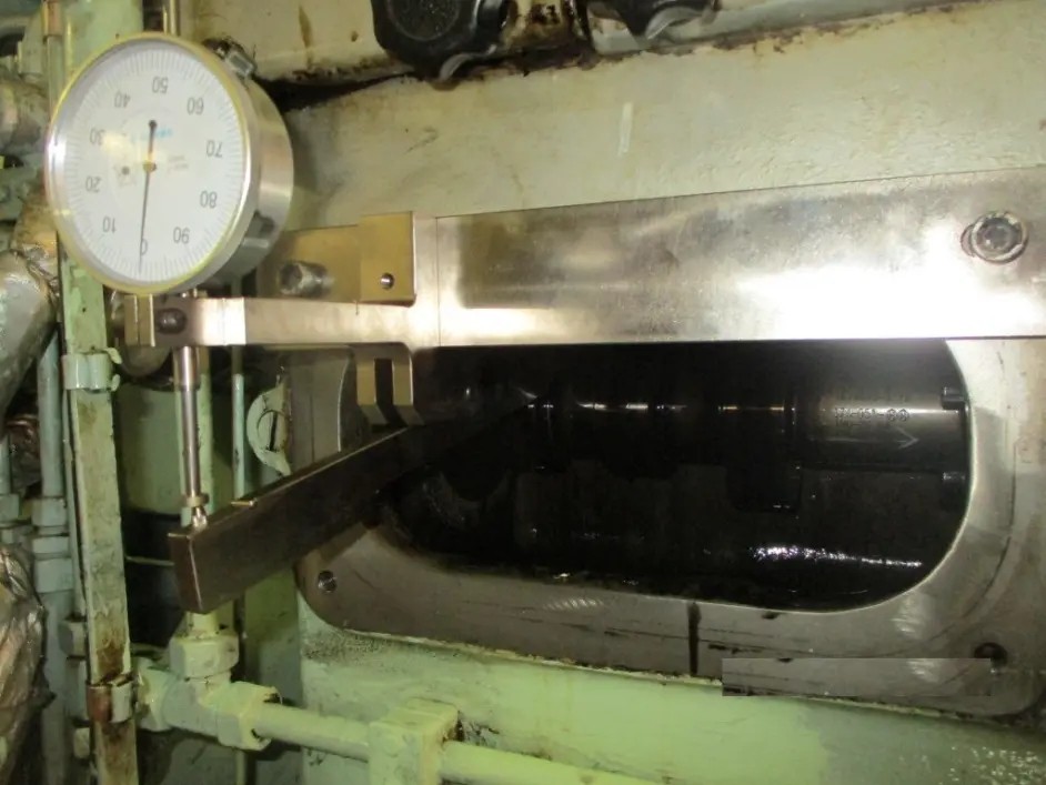
Slowly turn the engine flywheel in the running direction. Dial start to move as soon as follower starts rising (rise of cam starts). Keep turning the engine until the TDC mark (ignition DC) for cylinder unit no.1 is reached. Read and note down the dial gauge value.
Follow the procedure for all the cylinder units. Compare the value with maker’s data for pressure and tolerances.
Posted in: Diesel Engines, Motor Engineering Knowledge | Tagged: camshaft alignment, fuel pump lead, fuel pump lead measurement, fuel pump lead measuring device, fuel pump timing
作者:轮机英语学习频道 https://www.bilibili.com/read/cv14648806?spm_id_from=444.41.0.0 出处:bilibili
请登录后发帖
 联系我们人工客服


 :1391995811